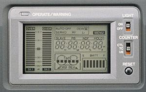
OPERATE WARNING indictor
- This LED indicator lights in OPERATE ON mode. It lights in green while
the VTR is operating normally.
- It lights or blinks in red in the case of a warning condition.
DA 1/DA 2 audio level meters
These are the signal level meters for the Audio 1 and 2 channels. They show
the input audio signal levels when the VTR is in EE or record mode. When
it is in play mode, they show the audio reproduction level of the audio
recorded on the tape. The peak levels are held for about 2 seconds.
Warning Indicators
- AUTO OFF indicator
Lights when a non-recoverable error (e.g. tape winding error, drum stopped,
etc.) occurs with the VTR. This indicator also lights if condensation
occurs.
- DEW indicator
- Lights when condensation (dew) occurs on the drum or other mechanism
in the VTR.
- The VTR rejects all operations while this indicator is lit.
- When the condensation has disappeared, the indicator turns off
and the VTR accepts operations again.
- SERVO indicator
Lights when the drum servo has trouble during recording to indicate
that normal recording is not being made.
- RF indicator
Lights when a video head is clogged. The head clog is detected during
back-space between different scenes. Note that it is not detected during
recording. Should this indicator light up, clean the head using the
special head cleaning tape: DCL5.
- Li indicator
Lights when the lithium battery which backs up data of the built-in
time code generator is nearly exhausted and indicates it is time for
replacement.
MENU indicator
Lights up when the VTR is in the setup menu mode by pressing the MENU button.
Time code-related indicators
SLAVE indicator
Slave lock indicator which lights when the built-in time code generator
is slave-locked (synchronized) with the LTC time code signal input at
the TC IN connector.
PB indicator
Time code playback indicator which lights when the time code is in playback
mode.
NDF indicator
Non-drop frame indicator which lights when the framing mode of the built-in
time code generator or the reproduced time code in the play mode is in
the non-drop frame mode. It lights permanently when the CTL counter
is in use.
Hold indicator
Lights when the time code generator display is held by pressing the HOLD
button in the time code setting block. The time code or user's bit can
be preset while this indicator is lit. Counter display
Usually, this section shows the data of the CTL counter, time code, users
bit, or sub-time code. The display mode can be selected with the COUNTER
switch.
- This section shows the setup menu data when the VTR is set to the
setup menu mode by pressing the MENU button. The setup menu also includes
the hour meter (drum usage).
- This section shows error code when an abnormal condition occurs
with the VTR.
Remaining battery power indicator
Shows the remaining battery power with a 7-dot segment bar display.
- To display the remaining battery power accurately, set the setup
menu item "BATT. TYPE SELECT" according to the type of the battery
pack in use.
Cassette/tape direction/remaining tape time indicators
- Cassette tape: Lights when the VTR is loaded with a cassette tape.
Blinks during ejection or tape loading.
- Tape direction: One of the indicator lights according to the tape
transport direction.
- Remaining tape: The remaining tape indication is shown with a 6
segment bar display.
LIGHT switch
Turns the display back light ON or OFF.
COUNTER switch
Selects the contents displayed on the LCD counter.
- CTL: Set to this position to display the CTL counter.
- TC: Set to this position to display time code or when presetting the
time code.
- UB: Set to this position to display the time code user's bits or presetting
the user's bit.
RESET BUTTON
- Press to reset the CTL counter value.
- Pressing the button during time code or user's bit presetting operation
resets the time code or user's bit data to "00:00:00:00"
|